How to Match a Proximity Sensor Output to a PLC Input
When an automated machine is commissioned, the most common integration failure is not a broken sensor. It is a mismatch between the sensor's output configuration and the PLC input it is supposed to drive. This guide explains how proximity sensor output types are selected, wired and verified against PLC inputs, drawing on the inductive and capacitive sensor platforms supplied by KJT Sensors.
Understanding the Two Output Families
Inductive proximity sensors detect metal targets through electromagnetic induction: the sensing face generates an alternating electromagnetic field, a metal target induces eddy currents that change the oscillation, and that change is converted into a switching output. Capacitive sensors work differently — the sensing face and surrounding environment form a capacitive circuit, and a target changes the dielectric constant and capacitance, which is processed into a switching signal. What matters for PLC integration is that both families deliver switching outputs, but they are configured across different options.
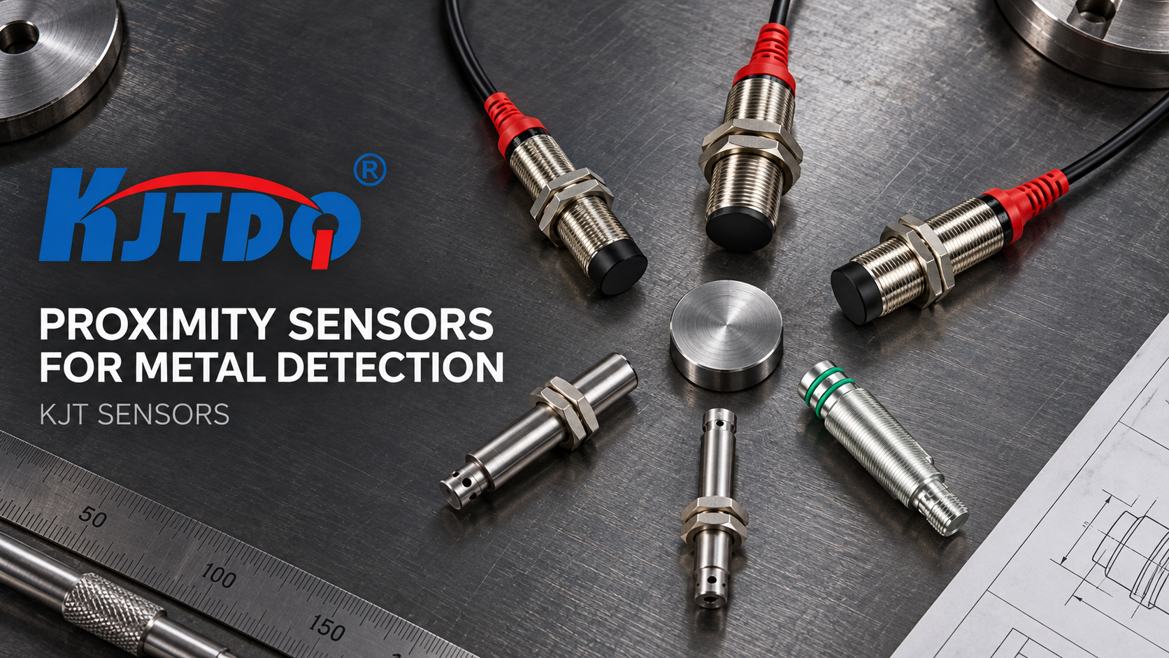
For inductive sensors, the available output configurations include NPN or PNP, two- or three-wire, normally open or normally closed, with AC/DC options, and connection to a PLC, relay, control cabinet or automated machine. Capacitive sensors support NPN, PNP and other switching outputs for connection to a PLC or control circuit.
Step One: Determine the PLC Input Type
Before choosing a sensor, establish what the PLC input module expects. The selection of PNP or NPN depends on the PLC input type and field wiring. These two conventions are effectively sink and source arrangements, and mixing them is one of the documented causes of integration failure — the sensor may function on the bench yet fail to register at the controller.
The KJT Sensors guidance is straightforward: select the output convention to match the PLC input type rather than adapting the controller to the sensor.
Step Two: Decide Between Two-Wire and Three-Wire
The next decision is two- or three-wire configuration. This should be based on the power supply, control system and existing equipment wiring. Three-wire sensors are common in modern control cabinets; two-wire devices are often used where existing equipment wiring already dictates the arrangement. Because the choice is tied to the supply and to what is already installed, reviewing the existing panel wiring before ordering avoids rework.
Step Three: Fix the Switching Logic
Normally open and normally closed outputs determine the resting state of the signal delivered to the PLC. The correct choice follows the machine logic — whether the PLC should see an active signal when the target is present or when it is absent. This is a control-architecture decision, not a sensor-performance decision, and it should be settled before the model is specified.
Step Four: Match Sensing Distance and Target Material
Output configuration is only half of the integration equation. Sensing-distance and target-material mismatches reduce detection stability. An inductive sensor is specified for metal targets — in-position detection, position detection, counting and limit detection. If the application involves non-metals, the integration problem is not a wiring issue at all; an inductive device simply is not the right sensing platform.
Capacitive sensors extend detection to metallic and non-metallic media, including liquids, powders, granules, plastics, glass, wood, paper and rubber, and can detect through non-metallic container walls. Where a capacitive sensor is used, field sensitivity is normally adjusted for the material and sensing distance, because dielectric constants vary by material. That adjustment affects how reliably the switching output reaches the PLC.
Step Five: Account for the Operating Environment
The integration plan must also survive the environment. A standard proximity switch cannot be used at high temperatures — a high-temperature series is required. Likewise, a standard switch cannot be used in an explosion-hazardous area; an intrinsically safe NAMUR device or another suitably certified explosion-proof product must be selected and configured in accordance with the site's explosion-protection requirements.
KJT Sensors builds inductive variants covering standard, remote, sanitary, high-pressure, high-temperature, analog output, explosion-proof, full-metal, ultra-small, intrinsically safe NAMUR, corrosion-resistant, ring-type, square, distance, weld-spatter-resistant, wireless and correction factor = 1 series. Capacitive variants include standard, high/low-temperature series, square series, and compact cylindrical and flat designs. These variants exist precisely so that control-system compatibility and environmental compatibility can be satisfied in the same order.
Mounting and Installation Compatibility
Mechanical fit is the last constraint. Inductive sensors support flush and non-flush mounting in cylindrical, rectangular, ring and flat designs, with M8, M12, M18 and other sizes for small-space or conventional installations. When installation space is limited, sensor placement becomes a genuine engineering problem, and the mounting format must be resolved alongside the electrical interface.
A Practical Selection Sequence
A reliable sequence for matching output to input is:
- Identify the PLC input type and confirm whether NPN or PNP is required.
- Confirm whether existing wiring calls for a two- or three-wire device.
- Define the required switching logic — normally open or normally closed.
- Verify the target material to choose inductive or capacitive sensing.
- Check environment: temperature, explosion-hazardous area, corrosion, weld spatter, pressure.
- Confirm mounting: flush or non-flush, housing format and size.
- Specify cable or connector, operating voltage and IP rating.
- Review the quotation against the configuration before ordering.
Because KJT Sensors quotes on product series, housing size, sensing distance, mounting and output configuration, cable or connector type, operating voltage, IP rating, temperature rating, explosion-protection, corrosion and weld-spatter resistance, wireless or analog requirements, order quantity and customization, standard models can be quoted quickly once the model and quantity are known. Special-environment, import-substitution and non-standard designs require technical review of the site conditions, original model specifications, mounting arrangement and control-system interface before quotation.
Why Interface Discipline Pays Off
Non-contact detection eliminates physical contact between the target and the sensing element, reducing wear and maintenance downtime compared with contact-based mechanical switching. It also supports high switching frequency and high detection accuracy. Those advantages are only realized, however, when the electrical interface is right: a wear-free sensor that does not register at the PLC delivers none of them.
Integration rarely fails because the sensing principle was wrong. It fails because output type, wire count, switching logic and PLC input were never reconciled — a small amount of interface discipline before ordering removes the risk entirely.
https://www.kjt-sensors.com/
KJT Sensors